FOUR RAM TYPE STEERING GEAR
Mateirals :-
a) Cylinders - Cast steel construction fitted with gunmental bushes.
b) Rams - Forged steel, working surfaces ground and highly finished.
c) Crosshead - Cast steel, gunmetal lined.
d) Pipework - Seamless solid drawn pipes, with forged steel flanges.
e)
Valve bodies - Forged steel.
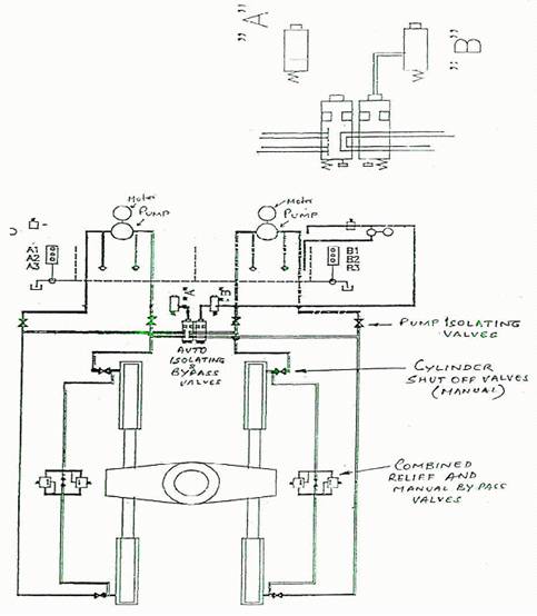
Valve arrangement :
Consists of four group of valves -
i) Four Pump Isolating Valves (manually operated).
ii) Four cylinder shut off valves (manually operated).
iii) Two combined relief and manual bypass valve. Relief valves set at 173 bar.
iv) Two combined automatic Isolating and Bypass valves with their associated solenoid operated servo pilot valves.
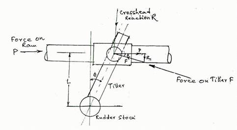
TORQUE ON STOCK :
Force
on Ram =.P
![]() = Helm or
Rudder Angle
= Helm or
Rudder Angle
Crosshead Reaction = R L = Distance-of stock from Ram.
.•. Force perpendicular to Tiller Arm = F
Torque on Rudder Stock = Force perpendicular to the Tiller x Lever Arm
=
F x L \ Cos![]()
Form
triangle of forces, F = P \ Cos![]()
Torque
on
stock = P \ Cos![]() x
L\
Cos
x
L\
Cos![]() = P.L \
Cos2
= P.L \
Cos2![]()
Mechanical
Advantage = P.L \ Cos2![]() \ Cos2
\ Cos2![]() =
1\ Cos2
=
1\ Cos2![]()
It is seen that as helm angle 8 increases, Cos0 decreases, Cos26 decreases further and the torque on stock increases.
(Formulae for assessing rudder torque's are based upon the expression Ta ACpV2 Sin q where:-
T = rudder torque, C = rudder area, Cp = centre of pressure distance from centre line of rudder stock, V = velocity of ship, q = rudder angle measured from mid-ship position)
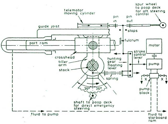
FOUR RAM ELECTRO-HYDRAULIC STEERING GEAR :
Two independent electrical supply cables one from main busbar and another from emergency busbar are laid to the steering gear compartment separately. Cables provide electrical power supply to steering motors through fuse switch units having HRC fuses and power contactors. Only short circuit protection is provided by way of fuses to the motors. Sustained overload protection is not provided as per Regulation, however, motor overload audible alarm and visual indication are incorporated to give early indication for failure of main supply, the circuit changes over to emergency bus supply automatically which gets energised within 45 sec. of failure of main supply. The motor insulation should be of class F or H to withstand the overload current.
OPERATION :
In the event of loss of hydraulic oil from one power actuating system, the loss can be detected and the defective system automatically isolated.
With Unit 'A' pump running with all four rams and Unit 'B' pump stopped, all valves opened excepting the automatic bypass valves. Oil levelin tank 'A' goes down to level A1, then audible and visual alarm sounds on the navigating bridge as well as in the machinery space. When the oil level in tank 'A' reaches to level A2, then automatic isolation valves closes and automatic bypass valve of system B opens, splitting the system into two.
The
system operates on one pair of rams, the bypass on the other having
been opened. The torque available will be half of that available with
four rams. The ship speed must be reduced as only 50% torque
available, bridge should be informed. There will be an out of
balance force on rudder stock (stock now subjected to
bending and
torsion).
3) If there is no further oil loss the system continues "as set" as hydraulic integrity exists.
4) If however, the oil level in tank A further reduces to level A3, alarm sounds again, then Pump A stops, Pump B starts, automatic by-pass valve of system B closes and system A opens: System B comes into operation with other two rams and system A gets completely isolated.
5) Similarly with System B operating originally and System A off, identical automatic change over will take place isolating the defective unit.
6)Also for both unit running simultaneously, whichever unit found to be defective will be automatically isolated by the actuation of level switches and automatic isolating and bypass valves.
ELECTRO-HYDRAULIC STEERING GEAR